Dual-channel ultra-high frequency RFID fixed reader FU-M6-M
This manual provides product installation, use, maintenance and other characteristic information, which can be read and used by product installers, users, and maintenance personnel.
- Overview
- Specifications
- Product Introduction
- Instructions for use
- Daily maintenance and repair
- Recommended Products
Overview
Product Introduction
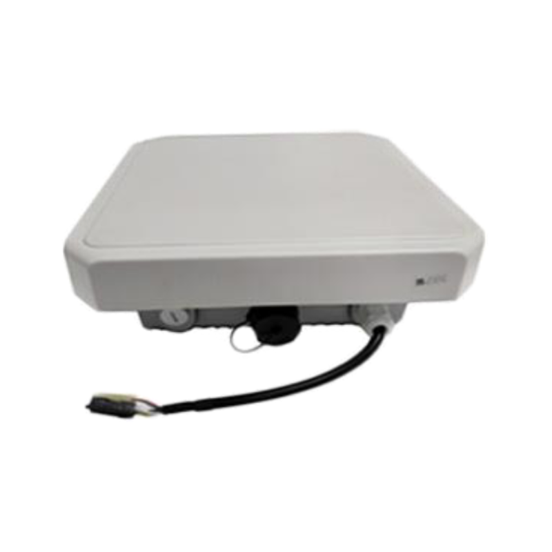
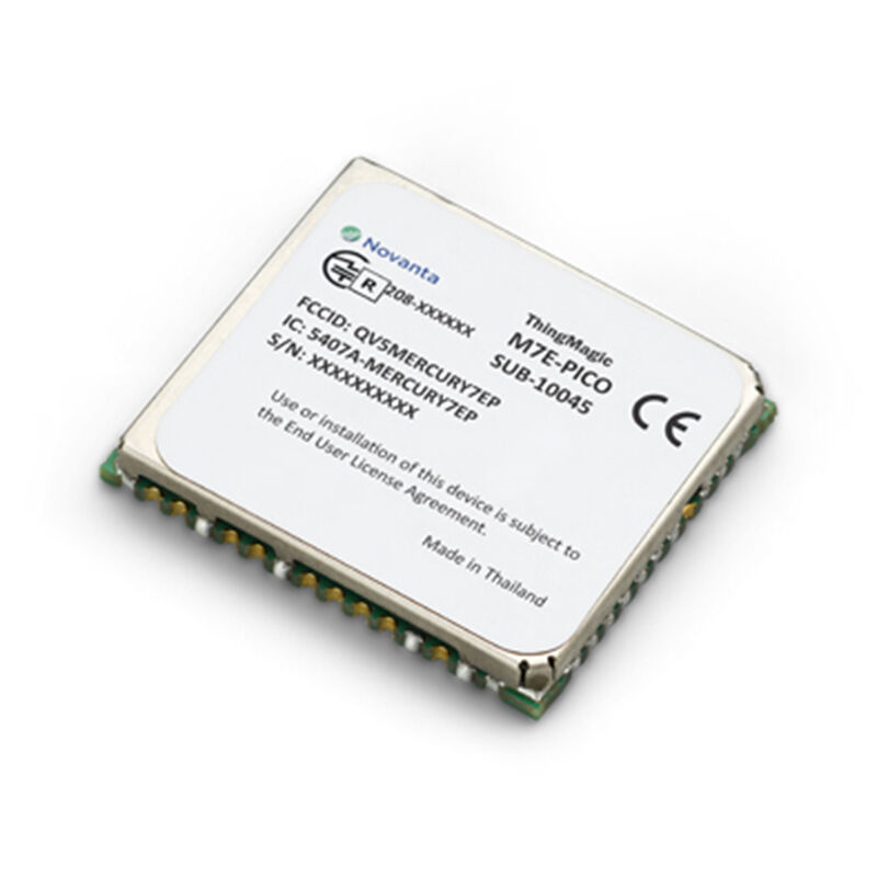
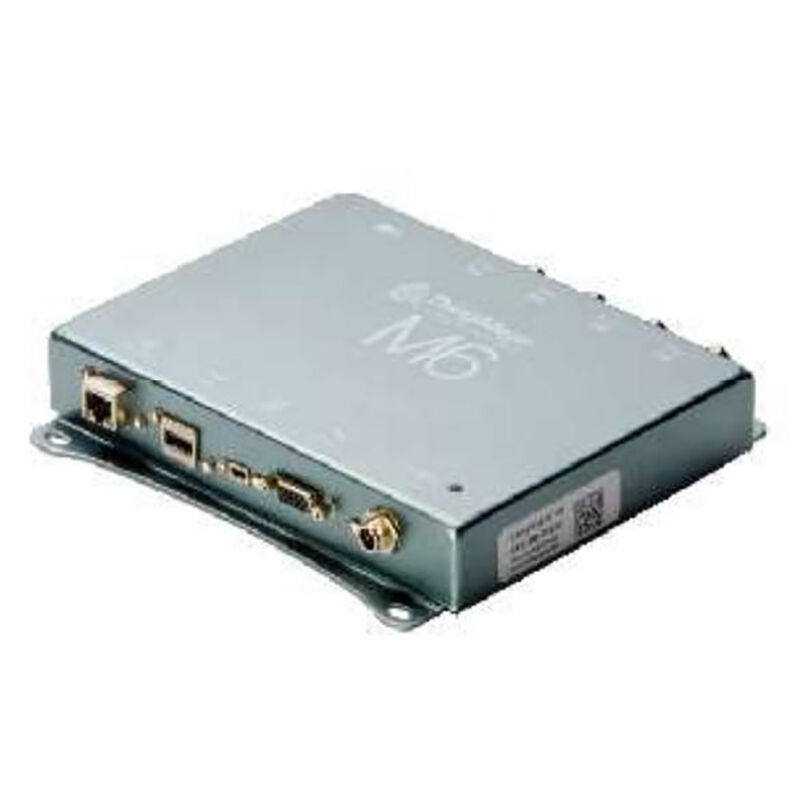
The FU-M6-M UHF RFID reader is an industrial-grade dual-channel RFID fixed reader integrated with the M6e-A module of the ThingMagic series as its core. It adopts a high-quality sheet metal casing, provides 2 TNC antenna interfaces, supports 2 independent antennas, offers dedicated communication and power interfaces, has an elegant appearance, and is easy to install and use. With an IP56 protection rating, it is suitable for various industrial and commercial environments and can meet the harsh working conditions of high and low temperatures. Widely adaptable to. It is used in various industrial and commercial environments such as convalescence, hotel laundry, smart healthcare, and new retail.
Product Features
The FU-M6-M ultra-high frequency RFID reader is a 4-4 dual-channel RFID reader. The FU-M6-M supports multiple UHF RFID protocols such as EPC Gen2, ISO18000-6B, ISO18000-6C, and IP-X (18000-6D). Authorization is required for use. And it supports automatic recognition of multiple protocols and mode switching.
The FU-M6-M industrial-grade RFID reader is designed in accordance with the EMC IEC61000-4 standard, meeting the industrial-grade wide voltage input mode. Both the power input and signals are isolated with an isolation voltage of 2KV. The wide voltage input and industrial-grade wide operating temperature range ensure an extremely long stable working time. Industrial-grade serial port/network port output, meeting the requirements of high-speed automatic real-time data transmission.
FU-M6-M fully exploits the advantages of Thingmagic RFID module modules. The tag chips around it support Alien H3, Impinj M series, NXP G2x* & G2i* series, and ID Cool Log tag chips, making it a must-have in the tag industry.
All Magic Mercury apis of FU-M-M and FU-M-M can fully support embedded operating systems and provide. The SDKS of NET and Java allow for easy customization of interfaces, thus enabling the necessary control over readers.
FU-M6-M provides dialogue support through the network and dialogue, and supports secondary development.
Specifications
| Tag Transfer Protocol | |||
| RFID Protocol support | IS018000-6C(EPC Classl Gen 2) | ||
| UHF RFID Antenna Interface | |||
| Antenna interface | RP-TNC*1 interface | ||
| RF power |
Read/write (transceive) separate mode Adjustable accuracy from 0dBm~27dBm/2W~5.5W, +/- 0.01dBm (when higherthan +15dBm) |
||
| Supported frequencybands | FCC (NA, SA) 917.4~927.2 MHz / ETSI (EU) 865.6-867.6MHz / TRAI (India)865-867 MHz/KCC (Korea)917-923.4 MHz / ACMA (Australia) 920-926 MHz/SRRC-MII (P.R. China) 920-925 MHz / MIC (Japan)916.8-923.4 MHz'Open' (Customizable channel plan; 859-873, 915-930 MHz) | ||
| Data/Control/Wireless Interface | |||
| WIFI | 802.11 a/b/g/n(optional) | ||
| RF interface | TNC *1 | ||
| External interface | RJ45*1 (10/100 Base-T Ethernet) / GPI0*4 / RS232 *1/ Power * 1 | ||
| Reset | Power off and restart | ||
| Structure size | |||
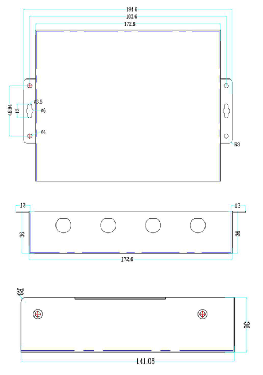
| Size | 195*141*36mm | Weight | 0.75 KG |
| Powered by | |
| DC power supply | 12VDC, Max DC power: 20 W |
| Surroundings | |
| Temperature | Working temperature: -20℃~+60℃; Storage temperature: - 40℃~+85℃ |
| Humidity | 5% ~95% (no condensation) |
| RFID performance | |
| Max tag cache | >10M bits |
| Tag read rate | >250 tag/s |
| Max EPC ID | 512 bits |
| Architecture | |
| Processor | Arm-Cortex A7 / Freescale i.Max (700mHz, 256 MB DDR, 256 MB Flash) |
| Operating system | Linux 4.4 |
| Network communication | TCP/IP or WIFI |
| Security Protocol | SSL/SSH-based security |
| Network IP | TCP/IP Static, WIFI Dynamic |
| Programming interface | |
| Host API | Java,C,C# |
| Authentication and Security | |
| Certification | Thingmagic M6e Module: Canada (Industry Canada RSS-21 0); EU (ETSI EN 302 208 v3.1.1,FCC47 CFR CH. 1Part15, RED 2014/53/EU) |
| Other | ROHS |
| Ordering Information | |
| TCP/IP | FU-M6 -N(1Port) |
Product Introduction
FU-M6-M is an industrial-grade dual-channel fixed reader integrated with Thingamgic's excellent M6e-Micro module. FU-M6-M adopts high-quality sheet metal housing, provides 2 TNC antenna interfaces, supports 2 independent antennas, and provides industrial-specific communication and power interfaces. It is compact in appearance and easy to install. The IP56 protection level is suitable for use in various industrial and commercial environments. , To meet the harsh working environment of high and low temperature.
 Main purpose and scope of application
FU-M6-M reader is a high-performance UHF reader. FU-M6-M supports EPCGen2&18000-6CUHFRFID protocol; and supports multi-protocol automatic identification and mode switching.
FU-M6-M is designed in accordance with the EMCIEC61000-4 standard and meets theindustrial-grade wide voltage input mode. The power input and signal are isolated. Theisolation voltage is 2KV. The wide voltage input and industrial-grade wide temperatureworking temperature meet the long and stable working time. ; Industrial-grade serial port\network port output to meet high-speed automatic real-time data transmission.
FU-M6-M gives full play to the advantages of ThingmagicRFID module algorithm, its excellenttag chip compatibility, supports AlienH3, ImpinjM series, NXPG2x&G2i* series, ID CoolLog tagchip, the uniqueness of the label compatibility industry.
FU-M6-M fully supports ThinglagicMercury API embedded operating system, provides SDK of . NET andJava, and can easily customize the interface to control the reader as needed.
FU-M6-M supports firmware upgrade through the network and serial port, and supports secondary development.
Do not disassemble or disassemble the reader device without the guidance of theauthorized personnel of the product manufacturer, otherwise, electric shock ordamage to the equipment parts may occur.Please don' t press or hit the reader device with heavy pressure, so as not todamage the parts or make the device operate abnormally.Please make sure that the power supply you are using is well grounded, otherwisethe accumulated static electricity will damage the device and the core RFIDmodule.
In the living environment, this product may cause radio interference. In thiscase, users are required to take measures to resolve the interference bythemselves. When not in use for a long time, turn off the power of the device.
Performance parameter
The main function
Labeling protocol: EPCClasslGen2 (IS018000-6C).
2-way TNC antenna connector, support 2 independent antennas.
Read and write (transceiver) separation mode from OdBm 30dBm/2. OW 5. 5W, +/-0. 5dBm adjustable precisionmaintenance: support remote maintenance and upgrade update.
Working mode: fixed frequency/frequency hopping optional.
Technical parameter
1. Working frequency: FCC902-928MHz (Americas)
ETSI865. 6-867. 6MHz (EU)
KCC-917-920.8MHz (Korea)
TRAI865-867MHz (MCIT; India)
ACMA920-926 (ACSTRALIA)
SRRC-MII (P.R. China) 920.1 - 924. 9MHz
2. RF output power: 30dBm (maximum output power)
3. Read label distance: ≥15m, use 12dBi antenna (6C protocol) >8m, use 12dBi antenna (6B protocol)*The writing distance is about 40% of the reading distance (In case of special circumstances, it depends on the performance of the label.)Network interface communication rate: 10M/100M adaptive
4. The tag recognition rate is greater than 750 tags/sec
5. EPC encoding 96 496bits
6. Embedded Linux operating system
Powered by
DC power supply: DC12V~24V, 2A power supply
Use environment
Working temperature:-20°C~+70°C
Storage temperature:-40°C~+85°C
Relative humidity: 5%~95% non-condensing sealed environment:
Protection grade IP65
ESDprotection
● Powersignal: I8kVcontact discharge;士15kVair discharge
● Antenna signal: ±4kV contact discharge; ±15kV air discharge
Size
volume parameters of FU-M6-M reader are:
Structural features and working principle
1. Overall structure and working principle
From its structure, FU-M6-M type reader is mainly composed of host unit, radiofrequency module unit, interface unit and chassis.FU-M6-M reader, tag, and PC (personal computer) form a complete reader applicationenvironment. Under the control of the PC, the host unit sends instructions to the radiofrequency module unit. The radio frequency module unit depends on the tag type. Aftersending out the corresponding instruction, the tag returns the correspondinginformation after receiving the instruction. The information is received by the radiofrequency module unit and then sent to the host unit and finally returned to the PC.
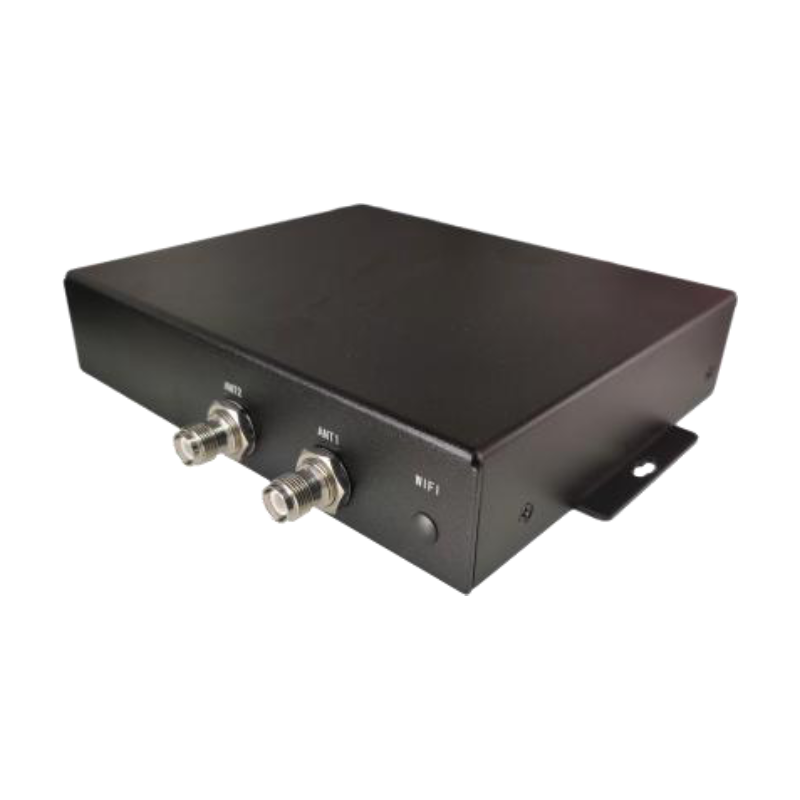
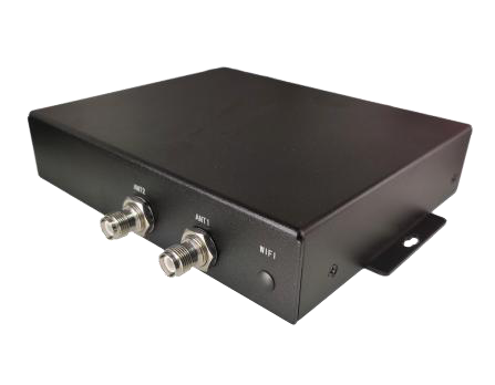
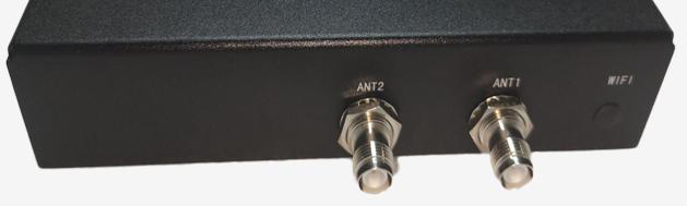
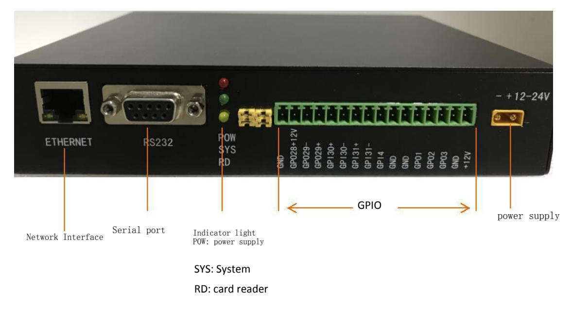
2. Panel description
The antenna port is used to connect to a TNC connector (male threaded inner needle).
Power supply, communication, GPIO and indicator panel.
The reader has an antenna connection self-check function. When the connectedantenna is a closed-circuit antenna, the reader will automatically select theconnected antenna; if the connected antenna is an open-circuit antenna, thereader will not be able to recognize it;When the reader does not recognize the antenna, it needs to seduce the antennamanually;
It is strictly forbidden to select the antenna port for card reading when theantenna is not connected.
3. GPIO interface description
Count from the power port, GPIO No. 1 to No. 16
| Number | Name | Function |
| 1 | +12v | Output 12V voltage |
| 2 | GND | Grounding |
| 3 | GPO3 | The GPO output has no pull-up or pull-down function. When the GPIO3 of the M6E module is internally connected, the module outputs a low level and the GPO outputs a low level |
| 4 | GPO2 | The GPO output has no pull-up or pull-down function. When the GPIO2 of the M6E module is internally connected, the module outputs a low level and the GPO outputs a low level |
| 5 | GPO1 | The GPO output has no pull-up or pull-down function. The GPIO1 of the M6E module is internally connected. The module outputs a low level, and the GPO outputs a low level |
| 6 | GND | Grounding |
| 7 | GND | Grounding |
| 8 | GPI4 | The GPI input has a 100K resistor pull-down. The GPIO4 of the M6E module is internally connected. When the external input is at a high level, the module detects a high level. When the external input is at a low level or not connected, the module detects a low level |
| 9 | GPI31- | For GPI input, first locate the ground of the external device. A: If the required trigger level is positive, GPI31- can be grounded and the trigger level connected to GPI31+. B: If the required trigger level is negative or zero (low level), GPI31+ can be connected to 12V and the trigger level connected to GPI31-. |
| 10 | GPI31+ | The GPI input can only be activated when positive and negative are used in combination. When the internal GPIO1_31 input of the core board is connected and there is no external input, the core board detects a high level. When there is an external trigger input, it detects a low level (the principle is that if the GPI31+ level is more than 5V higher than the GPI31- level, it will trigger). |
| 11 | GPI30- | For GPI input, first locate the ground of the external device. A: If the level to be triggered is positive, GPI30- can be grounded and the trigger level connected to GPI30+. B: If the level to be triggered is negative or zero (low), GPI30+ can be connected to 12V and the trigger level connected to GPI30-. |
| 12 | GPI30+ | The GPI input can only be activated when positive and negative are used in combination. When the GPIO1_30 input on the core board is internally connected and there is no trigger input outside, the core board detects a high level. When there is a trigger input outside, it detects a low level |
| 13 | GPO29+ | The principle is that if the GPI30+ level is more than 5V higher than the GPI30- level, it will be triggered. |
| 14 | GPO29- | empty |
| 15 | GPO28+12V | Power supply voltage output, with a 100K resistor pull-down, controlled by the core board GPIO1_29 for output, high output power supply voltage, low no output (100K pull-down) |
| 16 | GND | Power supply voltage output, with a 100K resistor pull-down, controlled by the core board GPIO1_28 for output, high output power supply voltage, low no output (100K pull-down) |
4. Description of auxiliary devices4
(1)Personal computer
The minimum hardware configuration requirements of the host:· CPU: Pentium 4, main frequency: 1. 7GHz or higher
Memory:512MByte.
Hard disk: 20G
10M/100M network interface
Host operating system requirements
Windows 2000 Service Pack 3; Windows Server 2003; Windows XPService Pack 2; Windows 7; Windows 8 系统
(2) Reader interface software
FU-M6-M type reader. NETAPI, VC and JAVA dynamic link library
RFID reader demo software
(3) Antenna
Impedance 502;
Voltage standing wave ratio: ≤1.4:1
Working frequency: meet FU-M6-M working frequency
(4) External RF cable
RF cable requirements: the maximum length should not exceed 10m, the impedance is 500,and the insertion loss is less than 3dB.
The long radio frequency cable will cause the attenuation of the transmitted signal and the receivedecho signal, which will degrade the performance of reading and writing.
Installation and commissioning
Please read this chapter carefully before installing the FU-M6-M reader.
1.Installation Precautions
In order to ensure your personal and property safety, you must make the following preparations beforeinstalling and using the FU-M6-M reader.
Measure and estimate the connection distance between the device and the system (such asreader and antenna, reader and PC, reader and power socket, etc. );
Check whether the installation position and direction of the reader and antenna willaffect the reader and electronic tag
Signal interference occurs during information exchange; when installing multiple readers/dense readers, pay attention to the antenna placement method of multiple readers and theminimum distance between the antennas to avoid mutual interference.
2. Installation conditions
Before installing the FU-M6-M reader, please carefully check whether the product is intact,whether the attached accessories are complete, and meet the required standards, and it canbe completed.
(1) Choose installation location
The antenna installation position should consider the minimum safe distance betweenthe antenna and the human body.
(2) Connect various devices
Connect readers, antennas, and PCs.
The auxiliary parts must be connected to each other in accordance with the designated equipment.When installing and connecting the antenna, pay special attention to the polarization matching betweenthe antenna and the electronic tag, otherwise, it will seriously affect the reading/writing distance ofthe reader to the electronic tag.
(3) install equipment
According to the on-site application situation, the read-write range of the reader and the connected antennais preliminarily determined. According to the on-site reading and writing test results of the FU-M6-M reader,Adjust the inclination (rotation) angle of the reader antenna to make the reading distance reach the bestcondition. Finally, fix the installation position and tilt (rotation) angle of the equipment.
3. Debug common problems
This section describes in detail the common problems in the debugging process, especiallythe general problems caused by incorrect installation, and explains how to correct them.The main common problems of debugging are as follows:
• No response from reader
The power indicator light is on check the relevant cable connection, and check the correspondingitem according to the status of the relevant indicator light;In the state of network port communication - check whether the connected IP is correct; checkwhether the IP address conf licts; whether the IP address and the host computer are in the same network segment; Whether the antenna number is set correctly.
• Read/write label error
Check whether the reader/writer protocol is compatible with the label protocol;
Check whether the reader configuration is correct;
The label placement position, whether the label is within the effective reading and writing range of thereader; whether there is electromagnetic interference between the readers or other equipment;
Whether the access password is required for label reading/writing, and whether the password is correct;
Whether the label is damaged.
• The read and write range does not meet the requirements
Check the antenna installation direction
Check whether the polarization mode of the antenna and the tag are the same
Whether the antenna selection supports the requirements of the read and write range
Whether there are interferences in the surrounding environment.
Instructions for use
1. Preparation and inspection before useThe demonstration software mainly performs system control, parameter setting, parameterquery, communication mode selection, reading and writing and display of radio frequency tagsfor the FU-M6-A reader. Provide C#, Java, instruction set development kits to facilitatesecondary development.
2. Demonstration software application environment
Software Environment
NETFramework4.0 and above
3. Demo software
Universal Reader Assistant Version 2.6.20.20
4. Demo software installation
This software is free of installation, just double-click UniversalReaderAssistant. exe, if it reports an errorwhen running, the error can be ignored.
5. Demo software operation
(1) DEMO start
Click Cancel, and the interface after startup is as follows:
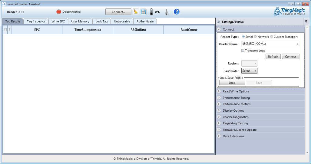
(2) Connect
Click the Connect button to expand settings/status;
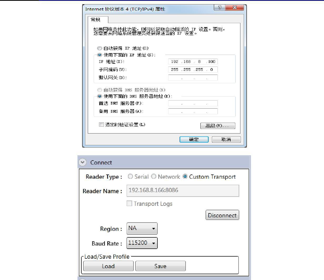
Network reader
Select NetworkReader, enter 192. 168. 8. 166 in the input box (the factory default IP of the reader)
Note: Before connecting the reader, please set the computer's IP to the same network segment as thereader, as shown in the figure below:
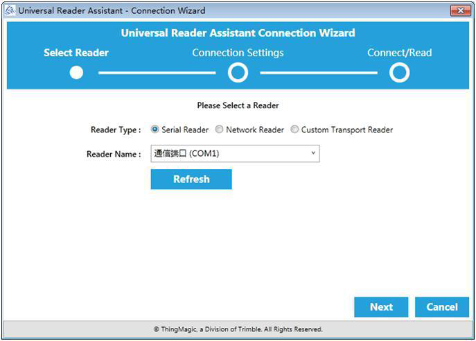
Serial port reader
Select Serial, select the corresponding serial port number in the drop-down box, and then click Connect:
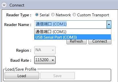
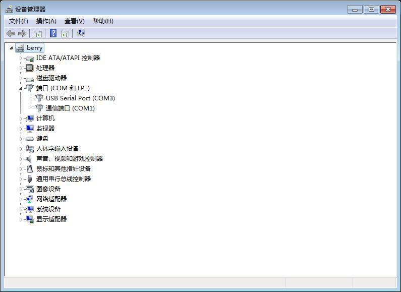
Note: You can view the serial port number in the device manager
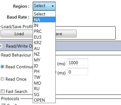
(3) Configure the working frequency of the reader
(4) Configure the working antenna of the reader
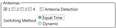
The closed-circuit antenna reader will automatically select it, and the open-circuit antenna needsto manually select the antenna number. Please remember the description of the antenna port of thereader in this operation manual, and after connecting the antenna, press the connected port andselect the correct port number to tick.
If multiple antennas are connected at the same time, the SwitchingMethod is selected as Dynamic:

Note: The checked antenna number must correspond to the port number of the reader one-to-one.and the port numberwithout an antenna connected cannot be checked, otherwise the reader will be easily damaged;
Improper selection of the antenna number will cause damage to the reader when the reader is working.
(5) Configure reader power
As shown in the figure below, ReaderPower is the read power setting:
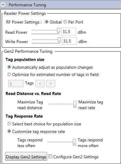
(6) Scene configuration
After checking "ConfigureGen2Setting", the GEN2 option will be expanded.
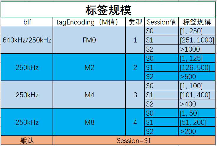
Several commonly used scene settings are provided below.
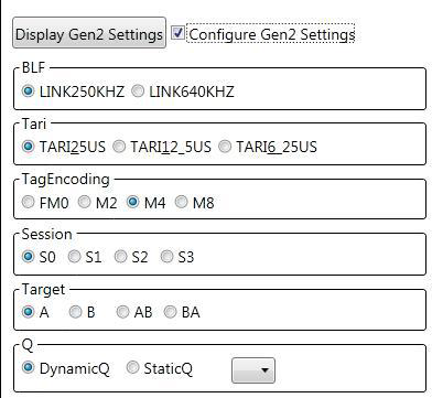
Commonly used configuration recommendations:
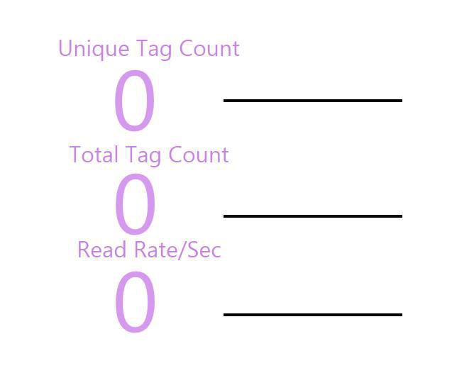
(7) Display options
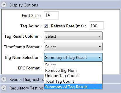
Through the "SunnaryofTagResult" in this option, the statistical data of reading tags can be displayed on the Demo main interface.
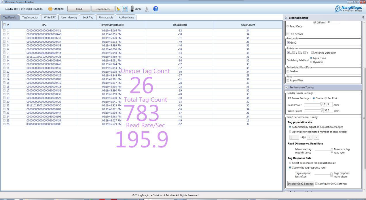
(8) Card reader
Click the Read button at the top of the interface

Example of reading results:
(9) Modify IP
The default IP of the reader is 192. 168. 8. 166, and the port number is 8086.
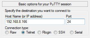
To modify the IP, putty is required. This manual uses putty VO.63. 0.0. 43510830 as an explanation.
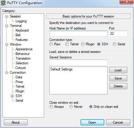
Select Connecttype as Telnet, enter the IP and its port, click Open, and the parameters are as follows:
After connecting the reader, enter the user name: fuwit, press Enter and then enter the password: 123456
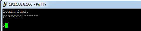
Enter at the cursor: ipsetip subnet mask gateway,press Enter; if the setting is successful,it willprint:

The complete example is as follows:

After the IP setting is successful, restart the reader to take effect.
Please keep in mind the ip address that has been successfully modified.
Daily maintenance and repair
1、Daily maintenance
Store in accordance with storage requirements.
2、Common failure analysis and solution
It mainly introduces the handling methods when the user encounters an abnormal phenomenon in the device during the use of the FU-M6-M reader.
The power indicator does not light up after power-on ☆ Power supply system failure: check whether the power supply is normal;
If other indicator lights are on, it may be an internal circuit failure.
Please contact our company for maintenance.
The network port cannot be connected
The default IP address set by the reader when leaving the factory is:192.168.8.166. When connecting, ensure that the IP address of the host computer and the IP address of the reader are in the same network segment, such as "192.168.8.XXX", which can be used for reading and writing. If you forget the IP address of the reader, please consult our company for a method to reset the IP.Shenzhen Fuwit Technology Co.,Ltd
Can't read card
☆ Whether the cable is connected correctly, the cable is not connected or the connection is not secure, which will cause the command of the PC to not be issued to the reader;
☆ Please check whether the antenna connector is tightened and the label is damaged;
☆ Ensure that the reader is properly configured.
For problems that users cannot solve by themselves, please contact our company to discuss maintenance matters.
After sale
When the user encounters an unsolvable problem when using this reader device, please contact our company.
Before the user contacts the company, please record the following information at hand:
If the company’s engineers determine that it cannot be solved remotely and decide that the user needs to return the reader for repair, the customer service representative will You will be given a return confirmation number RMA (ReturnMerchandiseAuthoriza-tion). Please write this number on the outside of the return system packing box, and write the number on a piece of paper in the packing box, so that the user's returned items will be processed quickly.
When returning the reader to repair service, please follow the steps below:
Carefully pack the reader and its accessories into the original anti-static foam packing box.
If the original packing box no longer exists, please choose a protective one;
Use filling materials to cover the contents of the box;
Add a note with the RMA number in the box;
Write the RMA number and the words "Fragile" on the outside of the box.